Activating a park can be a lot of fun. My Yaesu FT-891 and ATAS-120A Auto Active Tuning Antenna have done very well for me the last few years. But there are times when I like to add variety and try something different—perhaps a different rig or a different band or mode. That is what’s happening lately as I’ve been messing with linked dipoles. I’ve built a couple now. One covers 20M, 30M, and 40M, and I recently built another one that covers 6M, 10M, and 15M. I’ve been very pleased with both of them.
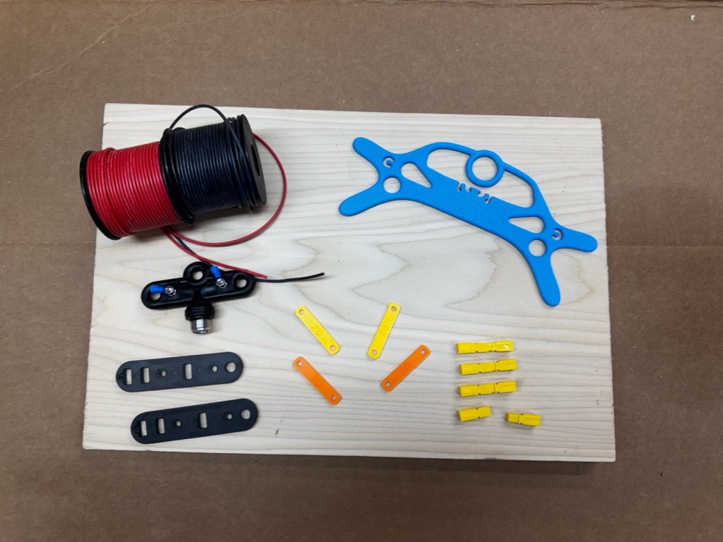
I used these antennas years ago, but put them away in favor of other configurations like EFHW, mobile hamsticks, etc. Last fall, I went along with Tim, AA4SS, to do some activations and he brought along his linked dipole. I’d forgotten how much fun they were. They are simple to deploy and work well. He left the antenna with me, and I was so impressed with it that I set out to build my own. I found they can be built using parts that are probably already in the average ham’s junk box.
Sourcing the parts can be even easier if you have access to a 3D printer. The only part I’ve not printed yet is the center insulator. I’m experimenting with 3D-printed center insulators, but so far I’ve had good results with the center insulators made by Moonraker and other manufacturers.
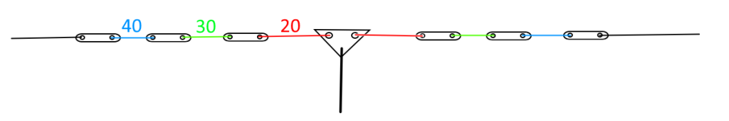
From a distance, the linked dipole will look like most other dipole antennas. But up close, you’ll see that the antenna is cut into multiple smaller sections, each representing a specific band. Changing bands is done by connecting or disconnecting various sections of the antenna (see below).
Band Switching Chart for the 20- 40 Meter Linked Dipole
| Band | 20M Link | 30M Link |
|---|---|---|
| 20 | Open | Open |
| 30 | Closed | Open |
| 40 | Closed | Closed |
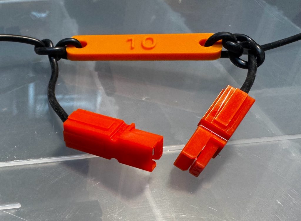
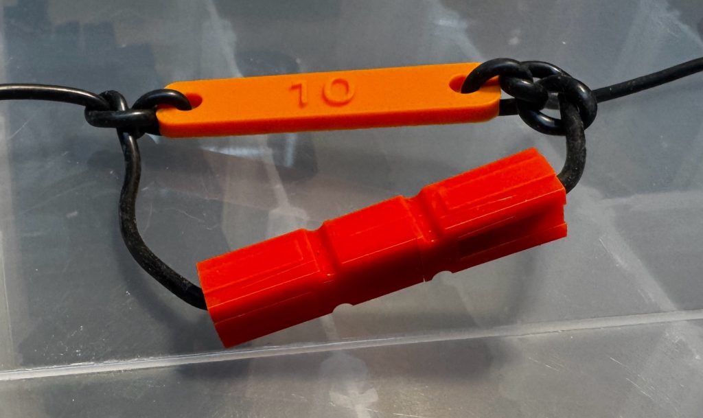
You can use practically anything to connect the sections while building this antenna, but I recommend using bare wires twisted together to connect the sections. After your antenna is complete, alligator clips, PowerPoles®, or any other connector that you have handy can be used. All that is required is that you are able to connect and disconnect the sections easily.
You can use any wire you choose. I prefer 18 AWG silicone wire since it doesn’t tangle as much as other types that I’ve tried. Also, I find that the 18 AWG wire is a good size for POTA use.
The linked dipole is lightweight and can be hung from a convenient support. It will hang from the center insulator from my telescopic fiberglass mast. For supporting the ends, I recommend plastic fence posts—the type used for electric fencing. They’re inexpensive and readily available from your local home center or farm supply store.
Building the Linked Dipole
The overall length of a linked dipole depends on the lowest frequency you want it to work at. For this example, we’re going to build a three-band dipole that covers 40, 30, and 20 meters.
| Band | Cut Length | Approximate Distance Between Insulators |
|---|---|---|
| 20M (14.2 MHz) | 16′ 5″ | 15′ 8″ |
| 30M (10.125 MHz) | 7′ 4″ | 6′ 5″ |
| 40M (7.150 MHz) | 10′ 4″ | 9′ 3-1/2″ |
As with most wire antennas, it’s best to cut your wires a few inches longer than necessary so you can tune for proper SWR. Test the SWR as you finish each section of the antenna. It takes longer this way but increases your chance for success. For that reason, the dimensions I list below are a bit longer than the calculated lengths.
20 Meter Section
The shortest elements (20M) will be 16′ 5″ per leg. Start by cutting two lengths of wire that are 16′ 9″ long. We get this number by applying the formula for a half-wave dipole (L=468/F). We’re shooting for 14.2 MHz. The formula will look like this: L=468/14.2. This gives us an overall length of 33′. Cut that in half, add a few inches, and we have 16′ 9″.
Attach one leg to each side of your center insulator. The other ends of the wires will then go to your first (20M) insulator. Leave a couple inches of wire sticking up from each insulator. Now take a moment to check your SWR on 20M and tune for best SWR if necessary. All good? Now let’s add your 30M legs.
Adding the 30 Meter Legs
Using the same formula, we find the total length of each 30M leg should be a bit over 23′. After subtracting the length of the 20M leg, you’ll be cutting your 30M legs to about 7′ 4″ each. Attach one end of each 30M leg to the unused end of the 20M insulator. The other end will attach to your 30M insulator. Do this on both sides of your antenna.
Take another break to check your work. You should have two wires sticking out from each of your 20M insulators and one wire sticking up from your 30M insulators. Tie the two wires on the 20M insulators together and test your 30M SWR. All good? Now for 40M.
Adding the 40 Meter Legs
The total length for each 40M leg will be around 33′. Subtracting the combined length of the 20M and 30M legs, you’ll be cutting your 40M legs to about 10′ 4″. Attach one end of each leg to the unused side of each 30M insulator and the other to the end insulators.
Attach rope to the unused part of the end insulators to support the ends of the antenna.
Now let’s do the final testing. Connect the wires on each of the insulators and test for best SWR on 40M. Once that is set, open your links (see link table) to test your SWR on 30M, then 20M.
When you’re happy with the operation on each band, attach your quick-disconnects and you are done. Congratulations! Now get out and activate a park!
If you would to read more about linked dipoles, the SOTAbeams website has a lot of good information, including links to handy calculators. (Find SOTAbeams portable antennas, masts, and more at DX Engineering.)
I hope this article helps motivate you to build an antenna for your next park adventure. Till next time, 73 and POTA ON!
Editor’s Note: DX Engineering’s Low Power Portable Dipole and Winder Kits make a great option for building your own lightweight single- or dual-band linked dipole. The antenna works well with a DX Engineering Nomad fiberglass telescopic mast.
The post Ham Radio Portable Insights: A Linked Dipole for POTA Activations appeared first on OnAllBands.